
Piping Analysis - Capabilities Overview

Marine and Offshore - Capabilities Overview

Sloshing in Partially Filled Vessels
Sloshing occurs in a partially filled vessel due to the movement of free surface liquid. The sloshing motion is a highly nonlinear and random process and depends on many parameters including gravity and viscosity effects. The applications are many including ship cargo and trucks transporting liquids like oil/gasoline.
Mechartes has been using its expertise in developing these models using modern mathematical and numerical tools like Computational Fluid Dynamics (CFD) and providing engineering services to the top-notch organizations (Consultants, EPC Contractors, Oil & Gas Companies etc.) across the globe.
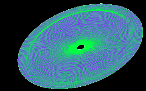
Simulation of Transient Temperature Distribution across Human Skin Tissue
This simulation is performed on a numerical solver that was developed at Mechartés and it takes into account the environment properties like temperature, humidity, wind velocity and solar radiation apart from biological parameters of the human body like blood perfusion rate, metabolic heat generation rate, thermal properties of various skin tissues etc.
What you see here is the thermal regulation initiated by human body across an 8 mm thick skin tissue when the temperature at a point in tissue is elevated to a mildly higher temperature. The Skin Tissue that is simulated consists of layers with different thermal properties of skin tissues like epidermis, dermis and sub-cutaneous layers.
This solver has been validated and can also be used in wide array of applications like studying the severity of fire hazard on human skin to evaluating the thermal response to the human body in an air conditioned environment or any other harsh or severe environment.
CFD Analysis to Study the Wind and Heat-Island Effect due to Outdoor A.C. Units in an High Rise Building
Objective: To study the airflow around the project building & other buildings due to the effect of wind and effect of heat generated by outdoor air conditioners installed in high rise project building on other surrounding buildings in worst case scenario.For wind flow analysis the predominant wind direction of SW with average wind velocities of 3 m/sec in Mumbai is considered based on the ISHRAE weather data. Hence, in worst case scenario all 30 floors with 20 outdoor AC units in each floor were considered for total heat dissipation from the project building. The worst case conditions were simulated for 21st March at 22:00 which is assumed to be a condition when all the ACs were working. At that moment as per ISHRAE weather data the ambient temperature in Mumbai is 26.9 C, same was considered in the CFD analysis.

Modelling and Analysis: Based on the provided CAD drawings details of the “Kahprideo project building & surrounding buildings”, the 3D CFD model was prepared. The area of interest for the project building & its surrounding building is 305m width, 340m length & 125.5m height. After preparing the 3 D geometry, the high quality mesh with different hexagonal & tetrahedral mesh was generated with total mesh cells of 8.8 million cells were obtained. The meshed geometry was used for solving the flow & energy equations in “project building & surrounding buildings” with applying the suitable boundary conditions in worst case conditions to see the effect of wind flow around buildings and heat dissipated by outdoor air conditioners on other buildings.
Also Read: Case Study - Boiler Combustion Analysis

Conclusion: Thus CFD Analysis was carried out to study the airflow around the project building & other buildings due to the effect of wind and also the effect of heat generated by outdoor air conditioners installed in high rise project building on the other surrounding buildings in worst case scenario. From the analysis it was found that the temperatures created due to outdoor air conditioners located in project building were reaching at lower levels to other buildings, however the temperature of this heat wave is 0.8 C above the ambient temperature & this temperature difference is very negligible. However while closely observing all the temperature results it reveals that just few meters away from the project building the temperature dropped to 27.6 C, then after 45m of distance the temperature is dropped to 27.2 C and then after 480m of distance the temperature dropped to ambient conditions. Hence it was concluded that the outdoor air conditioning units placed in the building were slightly affecting the surrounding buildings however it was almost negligible.

Acoustic Analysis of an Automobile Horn

Objective: D65 is a type of horn of Diameter 65mm and mainly consists of a resonator and a diaphragm which are separated by an air column which is responsible for the functioning of the horn. The resonator of the horn is 0.6mm in thickness and attached to the diaphragm with the help of a washer. The resonator consists of three humps in its design. The functioning will be best when the frequency of the air gap and resonator match or are almost equal and this is analyzed by various FEM methods.

Methodology and Analysis: By using FEM we can easily find out the frequency of the resonator but the frequency of the air column is a fluid-solid interaction(FSI) problem. Advanced FEM algorithm was used for the air column frequency and then by iterative method the frequency of both were matched . From the analysis done, some factors which can improve the design are modifying the dimension of the washer between resonator and diaphragm, like 0.5, 0.8, 1.0 etc and modification in the thickness of the resonator. Analysis is done by using different thickness of the resonator for different dimension of the washer. Few of the results are shown in the image.
Result and Conclusion: From various analysis done it can be concluded that the dB and quality of sound depends on the natural frequency of the air column and natural frequency of the resonator. Smaller the gap the better will be the quality of sound in the particular range. Since 0.6mm is the actual thickness of the resonator which upon analysis was modified to 0.4mm so that the air column volume was increased and hence the quality of sound improved. After changing the thickness and the profile the output is found to be good i.e. 0.4mm thickness and base is up from second hump and outer side by 0.8mm. Hence the resonator design was optimized to produce maximum sound with high quality.
Pulsation Analysis For High Pressure Petroleum Pipelines

Objective: Piping systems are a central part of numerous engineering installations. A number of sources such as pumps generate vibrations which can propagate along the pipes and excite other structures. These vibrations can cause two main problems, namely mechanical fatigue and acoustical noises. Further, interaction of the dynamic flow generated by the pump plungers with acoustical resonances in piping systems can result in high pressure pulsation levels pump and piping, cavitation, excessive vibrations and failures. Moreover, higher frequency fluid borne noise can be generated from flow perturbations associated with elbows, valves or cross section changes in the pipe. This design approach in conjunction with pulsation simulation is required to couple technical analysis of piping system to ensure that the piping will have adequate supports and clamps to maintain mechanical natural frequency of major acoustical energy.
Modeling and Analysis: The first design approach involved pulsation and vibration control through the use of good piping layout and support principles, adequate suction pressure and use of pulsation control devices such as dampers, accumulators, preventers, hydraulic isolators, inhibitors, suppressors, stabilizers, acoustic filters and selected piping configurations.The acoustical simulation techniques predict the potential of cavitations and the required minimum suction to prevent cavitations, based on amplitudes of the pulsations. The results obtained from the analysis proved that the pulsation levels at the suction end were considerably reduced and the pulsation levels were found to be under API 674 standards. Based on the pulsation amplitudes at various frequencies harmonic loads acting on the pipelines were calculated. These harmonic loads were applied at respective nodes and a FEM based harmonic analysis was done to determine the natural frequency of the system and response of the system to harmonic loads arising from pressure pulsations.

Conclusion: From the analysis the pipeline was first tested for the given set of pulsation damping equipments and reciprocating pumps. It was observed that the old configuration did not provide the desired pulsation control in the system. We observed amplification in pulsation in the suction side which was much above the values accepted by API and cavitations were observed at the suction end of the plunger. To reduce the pulsation it was therefore suggested that an additional pressure dampening equipment of size 1 liter must be installed 0.55 m from the suction end of the reciprocating pump. Further the analysis done on the pipeline with the additional dampening accumulator shows considerable reduction in pressure pulsation and the pulsation amplitudes were much below the allowable limits